
In 1909, German engineer Hans Beggerow patented an antenna design for Zeppelin airships. The wire trailed behind the gondola, a deliberate choice. Moving the high-voltage points away from the hydrogen-filled envelope reduced the risk of ignition. By 1936, ground-based operators had mounted the same configuration vertically, and its shape gave it a name: the J-Pole.
2.2 dBi
Typical gain – equivalent to a center-fed dipole
Calculate Your J-Pole Dimensions
Enter your target frequency below. The calculator derives all dimensions from the wavelength formula, applying a 0.95 velocity factor (standard for bare copper in air). Results are starting points, expect to trim during tuning.
What is a J-Pole Antenna?
The J-Pole is an end-fed half-wave dipole with a built-in impedance matching section. The half-wave element does the radiating. The quarter-wave stub below it transforms the high feed-point impedance, somewhere between 2,000 and 4,000 ohms, down to a value your 50-ohm coax can handle.
½λ
Radiator element
¼λ
Matching stub
Why Builders Choose J-Poles
No ground plane required. Unlike a quarter-wave vertical, the J-Pole doesn’t need radials. Mount it on a PVC mast, hang it from a tree, tape it to a window. The design works.
Omnidirectional pattern. The radiation pattern resembles a doughnut – equal signal strength in all horizontal directions, with a low takeoff angle (10–20 degrees) suited for line-of-sight VHF/UHF work.
Simple construction. Copper pipe from a hardware store, some solder, a coax connector. Total materials cost: under $25 CAD.
“A J-pole is an imperfect antenna that happens to do a very good job as a practical antenna.”
— L.B. Cebik, W4RNL (SK)

J-Pole Design Formulas Explained
All dimensions derive from wavelength. The speed of light divided by frequency gives the wavelength in meters. From there, the math is straightforward:
λ = 299.792 / f
Wavelength (meters) where f is frequency in MHz
Radiator Length (Half-Wave)
L radiator = 142.65 / f
Radiator length (cm) – applies 0.95 velocity factor
This is the main radiating element. In imperial units: 468/f gives feet. The velocity factor accounts for the slower propagation speed in real conductors versus free space.
Stub Length (Quarter-Wave)
L stub = 71.33 / f
Stub length (cm) – quarter wavelength × 0.95
The stub is shorted at the bottom. Its job: transform impedance. The characteristic impedance depends on conductor spacing and diameter – wider spacing increases it.
Feed Point Position
L feed ≈ L stub × 0.125
Feed point from bottom – approximately 1/8 of stub length
The 50-ohm impedance point typically falls 10–15% up from the shorted end. Start at 12.5% (1/8). If your SWR meter shows a mismatch, slide the tap point up or down in small increments.
Element spacing: 2.5–4 cm (1–1.5 inches) for VHF copper pipe builds. Wider spacing increases bandwidth but affects the feed point location.
Common Frequencies & Pre-Calculated Values
Reference table for popular amateur and license-free bands. All values assume VF = 0.95 (bare copper wire). For copper tubing, use 0.92 and shorten dimensions by ~3%.
Freq (MHz) | Band | Radiator (cm) | Radiator (in) | Stub (cm) | Stub (in) | Feed (cm) | Feed (in) |
|---|---|---|---|---|---|---|---|
144.0 | 2m | 98.9 | 38.9 | 49.5 | 19.5 | 6.2 | 2.4 |
146.0 | 2m | 97.5 | 38.4 | 48.8 | 19.2 | 6.1 | 2.4 |
440.0 | 70cm | 32.4 | 12.8 | 16.2 | 6.4 | 2.0 | 0.8 |
446.0 | 70cm | 32.0 | 12.6 | 16.0 | 6.3 | 2.0 | 0.8 |
151.82 | MURS* | 93.8 | 36.9 | 46.9 | 18.5 | 5.9 | 2.3 |
462.56 | GMRS† | 30.8 | 12.1 | 15.4 | 6.1 | 1.9 | 0.8 |
💡 Cut Long, Trim Short
Add 2–3% to calculated lengths when cutting material. You can always trim an antenna that’s too long, adding material back is harder. Use an SWR meter to find resonance, then trim in 5mm increments.
Construction Tips & Materials
Building a J-Pole requires basic tools and readily available materials. The antenna can be constructed in an afternoon with a hacksaw, soldering iron, and a tape measure. Choose your material based on intended use – permanent installation or portable operation.
Material Options
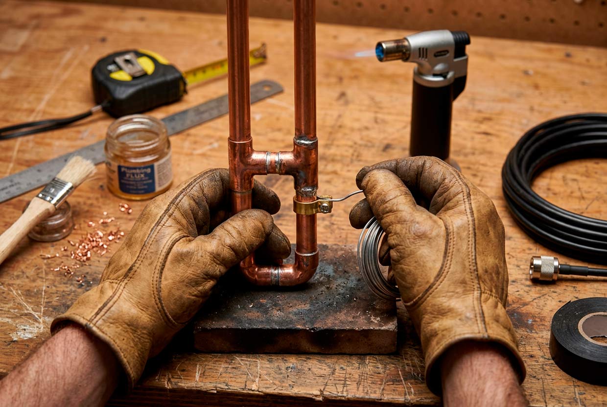
Copper pipe (13mm or 19mm / ½” or ¾”): The classic choice. Rigid, weatherproof, easy to solder. Available at any hardware store. A 2-meter J-pole requires about 1.5m of pipe total.
Aluminum tubing: Lighter than copper. Cannot be soldered – use hose clamps or mechanical fasteners. Corrosion-resistant if anodized.
Bare copper wire (12–16 AWG): Cheapest option. Makes a roll-up portable antenna. Edison Fong’s DBJ-2 design uses this approach.
300-ohm twin-lead: The “Slim Jim” variant. Folds into a pocket. Lower velocity factor (~0.82) – adjust calculations accordingly.
Installation Notes
Height: Get the radiator above obstructions. Every meter of height gain improves your signal.
Choke balun: Coil 3–5 turns of coax near the feed point (40mm diameter for 2m). This prevents RF from traveling back down the shield and becoming part of the antenna.
Weatherproofing: Seal the coax connector with self-amalgamating tape or Coax-Seal. Water in the connector destroys SWR.
Drip loop: Route coax downward before it enters the shack. Water follows gravity.
⚠️ Keep Away from Metal
Mount the antenna at least 2 meters (6 feet) from metal objects – gutters, masts, guy wires. Nearby conductors detune the antenna and distort the radiation pattern.
The J-Pole has survived since the Zeppelin era for a reason. It works. The calculations get you started. The SWR meter finishes the job.
Further Reading
- Radio Amateurs of Canada – antenna resources and band plans: rac.ca
- ARRL Antenna Book – Chapter 24 covers J-Pole theory and construction in depth
- Edison Fong, “The DBJ-2: A Portable VHF-UHF Roll-Up J-pole” (QST, March 2007)
- M0UKD Slim Jim and J-Pole Calculator: m0ukd.com/calculators
* MURS (Multi-Use Radio Service) is a US-only license-free band. License-free frequencies vary by country.
† GMRS (General Mobile Radio Service) is available in Canada and the USA with different licensing